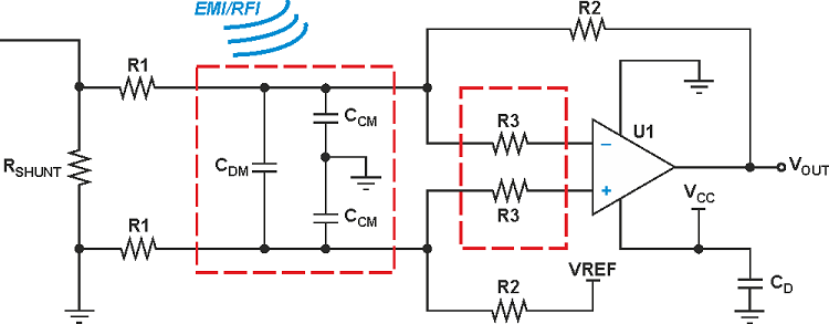
Filter design and selection depends on the EMI regulations, electrical specifications and other design requirements. For all analyses, which were performed using EMI Analyst software, capacitor values are again 100 nF, and inductor values are 1 micro H. An EMI Filter is required to protect electrical devices from electromagnetic interference (EMI). The same five filters analyzed for the 50 ohm system graph above are again analyzed below for three different combinations of source and load impedance. When filter component impedance is close to circuit impedance, the filter component has little effect. Insertion loss is greatest when the impedance of the filter component nearest the input terminals is a mismatch for the source impedance, and the impedance of the filter component nearest the output terminals is a mismatch for the load impedance. As a result, when a filter is installed in the circuit its insertion loss can be very different than when measured in a 50 ohm system.Īs illustrated in the following graphs, the in-circuit effectiveness of a filter is a function of both circuit impedance and filter topology. In-Circuit Insertion LossĬircuit source and load impedances are rarely 50 ohm, and usually vary significantly over frequency. Filter insertion loss if frequency-dependent, often changing several orders of magnitude over the filter’s useful frequency range, so it is convenient to express insertion loss in units of decibels (dB).Īs expected, above their respective corner frequencies, the C-section filter provides one-pole roll off (20 dB per decade), the LC-section and CL-section filters provide two-pole roll off (40 dB per decade), and the Pi-section and T-section filters provide three-pole roll off (60 dB per decade). The ability of the filter to remove unwanted noise from a circuit is called its insertion loss. Hardware design as well as FPGA implementation issues have been presented to prove the efficiency of the developed digital filtering structure. Numerically, the insertion loss of a filter is the ratio of the signal level at the input to the filter to the signal level at the output of the filter. The DM noise flows in line and returns by neutral whereas the CM noise flows in line and neutral and then, flows into ground. Moreover, conducted EMI is separated into two modes one is differential mode (DM) interference and another is common mode (CM) interference. Insertion loss is a measure of how much the filter attenuates a signal at a given frequency. The EMI filter is designed to reduce conducted noise emission. Digital and Analog circuit impedance in electronic systems varies significantly with frequency and is rarely 50 ohm.

Radio frequency test equipment most often has 50 ohm input and output impedance.

Why? End-use circuit impedance is almost always different than measurement system impedance. When selecting or designing a filter, it is important to understand that filter performance is different when the filter installed in the circuit than when measured outside the circuit. For electromagnetic interference control, passive low-pass filters are the most common type. How Circuit Impedance Affects Filter PerformanceĮMI filters are used extensively in electronic equipment to control electromagnetic interference.


 0 kommentar(er)
